

『Coriolis Flow Meter Diagram: Flanged Processing Spool Pipe Run Sizing Rules』Related information(v cone flow meter|rotary gas meter|gallon meter|gear meter|metal tube rotameter|glass tube rotameter|nutating disk meter|transit time ultrasonic flow meter|wedge flow meter|pd meters|hydraulic flow meter|ultrasonic water flow meter|water flow meter|air flow meter|magnetic water flow meter|oxygen flow meter|gas flow meter|argon flow meter|air velocity meter|gasoline flow meter|fuel flow meter|ultrasonic water meter|digital water meter|nitrogen flow meter|solid flow meter|Oxygen tank flow meter|digital water flow meter|diesel fuel flow meter|steam flow meter|02 flow meter|compressed air flow meter|oil flow meter|liquid flow meter)
Coriolis Flow Meter Diagram: Flanged Processing Spool Pipe Run Sizing Rules
Quick Answer: A flanged Coriolis flow meter needs a processing spool with the same bore as the meter, low pipe stress, and a short stabilization length. For most liquid service runs, zero to 2 diameters of straight pipe before and after the meter is enough. Send pipe size, pressure, temperature, and flow range to Silver Automation Instruments for a spool sizing check.
What the Flanged Processing Spool Diagram Shows
The processing spool pipe run sizing rules start with bore match. The diagram for a flanged Coriolis meter includes the process connection flanges, bolt holes, spool bore, gasket seat, and flow direction arrow. If the process pipe has a larger inside diameter than the meter tube, the flow profile changes at the flange face. This does not usually destroy mass flow accuracy. But it can cause pressure loss, cavitation, or unstable density readings on liquids with low vapor pressure.
Flange standards vary by region. In Southeast Asia we often see ASME B16.5 Class 150 or 300 flanges. In the Middle East and Africa, DIN PN16 and JIS 10K also appear. The spool must match the flange pressure class and bolt pattern. Do not mix Class 150 and PN16 bolt holes on the same joint. That creates a leak path and pulls the meter body out of alignment.
Pipe Run Sizing Rules for Liquid Service
Select a processing spool with the same nominal bore as the meter. For DN15 use a 15 mm bore. For DN25 use a 25 mm bore. For DN50 use a 50 mm bore. If you need a reducer, use a concentric reducer with a maximum included angle of 15 degrees. Avoid eccentric reducers on horizontal lines because they can trap gas.
Typical liquid flow ranges for Silver Instruments CMF series on water-like liquid with 1 cP viscosity are as follows. DN15 handles 0 to 1000 kg/h. DN25 handles 0 to 5000 kg/h. DN50 handles 0 to 30000 kg/h. DN80 handles 0 to 100000 kg/h. These ranges shift with density and viscosity. A lower density fluid produces a smaller mass flow signal at the same velocity.
Keep the pipe full. Do not install the meter at the highest point of a liquid line without a back pressure valve. Maintain downstream pressure at 1.3 times the fluid vapor pressure to stop flash cavitation. A paint manufacturer in Southeast Asia had a DN40 meter reading high because the spool was oversized and gas pockets collected at the flange. We fixed it with a matched bore spool and a lower flow range.
Pipe Run Sizing Rules for Gas Service
Gas service is different. Gas has low density, so the mass flow signal is smaller. Do not oversize the pipe at the meter. A DN15 meter on low pressure air or natural gas may need a minimum pipe velocity of 5 m/s to keep the signal stable. If the process line is DN40 and the meter is DN15, use a smooth reducer directly at the meter flanges. The reducer should not choke the flow.
Avoid liquid dropout in gas lines. Install a filter or coalescer upstream if solids or mist are
Flange Alignment and Pipe Support
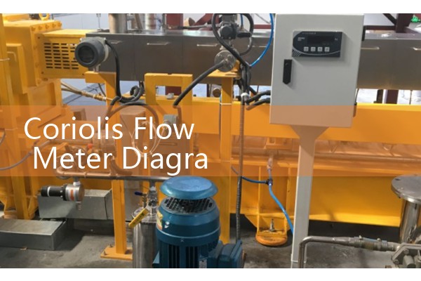
Here is the thing. Flange alignment matters more than straight run. Align both flanges to within 1 mm before inserting the meter. Use a cross pattern torque sequence. Do not pull the pipe into alignment with the meter bolts. That creates stress on the sensor tubes. Place pipe supports at 2D to 5D from the meter flanges. Do not use the meter as a pipe support. On vibrating lines, add a pulsation damper or flexible connector upstream, but keep the meter body fixed.
Recommended Silver Instruments Models
Silver Automation Instruments supplies flanged Coriolis mass flow meters from DN15 to DN200. Wetted parts are stainless steel 316L. Accuracy is 0.1 percent of rate for mass flow. Density accuracy is 0.0005 g/cm3. Temperature range is -200 to 200 degrees C. Outputs include 4-20 mA HART and pulse. Model matching for common spools follows. SIL-CMF-15 for DN15. SIL-CMF-25 for DN25. SIL-CMF-50 for DN50. SIL-CMF-80 for DN80. SIL-CMF-100 for DN100.
Send us your pipe size (DN), pressure (bar), temperature (degrees C), and flow range (kg/h). Call +86-135-1213-1526. WhatsApp 86-135-12131526. WeChat +86 13512131526. You can also check the product pages at flow-meter.com.au.
FAQ on Flanged Spool Pipe Sizing
What is the minimum straight run for a flanged Coriolis flow meter?
For most liquid lines, zero to 2D of straight pipe is enough. The meter measures mass directly, so flow profile damage has less effect. But you must control pipe stress and vibration.
How do I size the processing spool for a Coriolis meter?
Match the spool inside diameter to the meter inside diameter. Use the same schedule pipe. For DN15 use 15 mm bore. For DN25 use 25 mm bore. For DN50 use 50 mm bore. Avoid sudden steps at the flange face.
Can a Coriolis meter handle gas and liquid in the same line?
It can handle mixed phases for short periods, but slug flow causes measurement errors. Install a gas knockout for liquid lines or keep gas lines free of liquid dropout. If two phase flow is normal, tell us before sizing.
What is the recommended flow range for DN25 and DN50?
On water-like liquids, DN25 handles 0 to 5000 kg/h. DN50 handles 0 to 30000 kg/h. The best accuracy band is 10 to 100 percent of the nominal range. For very low flows, a smaller DN meter is often better.
What pipe support rules apply to a flanged Coriolis meter?
Place supports at 2D to 5D from the meter flanges. Align flanges within 1 mm before bolting. Use gaskets that do not enter the flow path. Tighten bolts in a cross pattern with a torque wrench.
 Hot Blog
 Related AD