

『Thermal Mass Flow Sensor Insertion & Alignment』Related information(v cone flow meter|rotary gas meter|gallon meter|gear meter|metal tube rotameter|glass tube rotameter|nutating disk meter|transit time ultrasonic flow meter|wedge flow meter|pd meters|hydraulic flow meter|ultrasonic water flow meter|water flow meter|air flow meter|magnetic water flow meter|oxygen flow meter|gas flow meter|argon flow meter|air velocity meter|gasoline flow meter|fuel flow meter|ultrasonic water meter|digital water meter|nitrogen flow meter|solid flow meter|Oxygen tank flow meter|digital water flow meter|diesel fuel flow meter|steam flow meter|02 flow meter|compressed air flow meter|oil flow meter|liquid flow meter)
Thermal Mass Flow Sensor Insertion & Alignment
Quick Answer: Thermal mass flow sensor insertion depth and alignment directly decide measurement accuracy. Wrong insertion depth can cause errors above 15 percent, especially in small pipes below DN80. The sensor must sit exactly in the center of the pipe and the flow arrow must match the real flow direction. Silver Automation Instruments ships every insertion probe with a depth gauge tool and laser-etched alignment marks to cut commissioning time on site.
Why Insertion and Alignment Are Not Just Installation Steps
We often receive calls from plant engineers who say the flow meter shows unstable readings. After 10 minutes of remote checks, the problem is almost always the same. The sensor is not deep enough, or the angle is off by a few degrees. Insertion thermal mass flow meters do not fail because of the sensor element itself. They fail because of poor mechanical placement.
In a DN100 compressed air line at an automotive parts factory in Thailand, a sensor installed only 60 percent into the pipe gave a flow reading 22 percent lower than the actual value. The pipe had a 3 mm internal scale layer near the wall. The sensor tip sat in a slower boundary layer, not in the main flow. After we guided the site technician to push the sensor deeper to the calculated center point, the reading matched the plant reference meter within 0.8 percent.
Here is the thing. Most engineers skip the insertion depth calculation and just push the probe until it feels tight. That is a mistake. Thermal mass flow sensors measure the cooling effect of the gas flow on a heated RTD. That cooling effect is a function of mass velocity at the exact point where the sensor sits. If the sensor does not sit in the fully developed flow core, the velocity profile error becomes a direct mass flow error.
Pipe Size Dictates the Insertion Depth Rule
Insertion depth is not a universal number. For pipes from DN40 to DN300, our rule is simple. The sensor tip must be at the pipe centerline. For pipes above DN300, we still aim for centerline, but sometimes we use a multi-point calibration profile because centerline velocity alone can overestimate total flow in very large ducts. Silver Instruments provides an insertion depth calculator as a printed card inside every shipment box. The formula is based on pipe inner diameter, pipe wall thickness, and the compression fitting height.
Example from a biogas plant in Brazil last month. DN150 schedule 40 carbon steel pipe, inner diameter 154 mm, wall thickness 7 mm. Compression fitting height was 42 mm. The correct insertion depth from the pipe outer wall is 42 + 7 + (154/2) = 126 mm. The installer had made a mark at 100 mm because he guessed. That 26 mm difference was enough to put the sensor in a lower velocity zone. After correction, the daily biogas mass balance closed properly for the first time in six months.
Sometimes, the pipe has a flow conditioner or a partially open valve upstream. In those cases, the velocity profile is asymmetric. We recommend rotating the sensor 90 degrees to sample a different plane, but only after checking the straight run requirements. For most installations, the sensor tip must look straight into the flow direction without any tilt.
Alignment Marks and Flow Arrow Are Not Decoration
Every Silver Instruments thermal mass flow sensor has a permanent flow direction arrow laser-etched on the probe body. There is also a flat machined on the compression fitting that must be parallel to the pipe axis. If the flat is even 15 degrees off, the sensor head faces the flow at an angle, and the flow over the sensing elements is no longer perpendicular. This creates a cosine error. A 15-degree misalignment produces roughly a 3.5 percent reading drop, which grows quickly at angles above 20 degrees.
We saw this at a nitrogen blanketing system in a chemical terminal in Malaysia. The operator installed the sensor with the arrow pointing opposite to real flow. The meter still gave a positive reading because thermal sensors respond to flow magnitude, not direction, but the cooling profile was wrong. The error was 11 percent at low flow and 4 percent at high flow. After we reversed the probe direction, the meter tracked the mass balance tank level perfectly.
For wet gas or saturated gas applications, alignment is even more critical. If the sensor head tilts downward, condensate can collect on the heated element and cause spike readings. The factory recommendation is to install the probe in the horizontal plane, with the flow arrow horizontal and the electronics housing upright. In vertical pipes with upward flow, the probe should be horizontal so that any liquid droplet falls away from the sensor head.<
The Depth Gauge Tool Prevents Guesswork
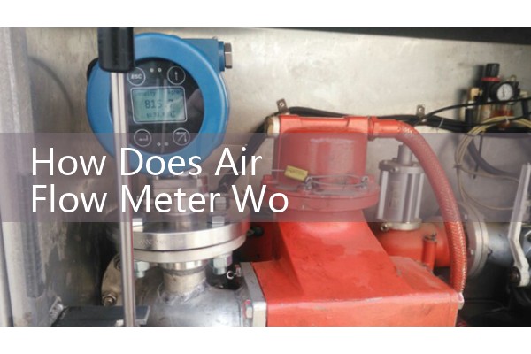
Silver Instruments ships a stainless steel depth gauge with every insertion meter. It is a simple rod with a locking collet. You set the calculated depth on the gauge, lock it, and use it as a physical stop during insertion. This tool removes the need to measure with a tape in a dark pipe gallery. One of our customers in a Vietnam steel plant cut their insertion time from 25 minutes per point to under 8 minutes just by using the depth gauge and the alignment flat.
In high-pressure gas lines above 10 bar, do not attempt to insert or retract the sensor under pressure unless the meter has a ball valve retractor assembly. The force on the probe stem can push the sensor out violently. Always use the retractor kit, and always check the insertion depth after the first thermal cycle because the compression fitting can settle by 0.5 to 1 mm and change the depth slightly.
Verification After Insertion: The Hot Tap Checklist
Once the sensor is inserted and aligned, do a quick verification. Close the ball valve downstream, fill the pipe with a known static pressure, and check that the flow reading is zero within the meter cut-off tolerance. Then open the valve and compare the meter output at several flow rates with a portable reference, if available. Adjust the insertion depth by small amounts and watch the reading. If the reading increases as you push deeper, the sensor was too shallow. If it decreases, it was past the center. The correct depth gives the strongest, most stable signal.
For pipes with insulation, the insertion depth calculation must include the insulation thickness and any jacketing. For example, a DN200 pipe with 50 mm mineral wool and 1 mm aluminum cladding requires that extra 51 mm be added to the stem length when calculating the insertion depth from the outer surface. Many installers forget this and end up with the sensor tip still inside the insulation space, reading near zero flow.
Common Mistakes and How We Help Customers Avoid Them
One, using the wrong distance piece. Insertion meters for gas service often come with a Teflon ferrule instead of a metal ferrule. If the installer swaps them, the compression seal leaks. Two, ignoring thermal expansion. A 2-meter-long probe in a gas duct at 150 degrees Celsius expands about 3.5 mm. That changes the tip position from center to off-center. Silver Instruments includes a thermal expansion compensation table in the manual. Three, not marking the insertion depth on the probe with a permanent marker after final tightening. This mark lets the maintenance team verify depth without tools next month.
Send us your pipe ID, wall thickness, gas type, pressure in bar, temperature in Celsius, and flow range in kg/h or Nm3/h. We will return a pre-calculated insertion depth, the recommended sensor type, and a wiring diagram within one working day. Visit our thermal mass flow meter page at flow-meter.com.au for the request form.
Thermal Mass Flow Sensor Insertion & Alignment FAQ
Q: What happens if the sensor tip is not exactly at the pipe centerline?
A: The flow reading will be biased low or high depending on the velocity profile. In most turbulent pipe flows, the error can range from 5 percent to over 20 percent. For laminar flows in small pipes, the error can exceed 30 percent because the velocity profile is parabolic and sensitivity to position is extreme.
Q: Can I install an insertion thermal mass flow meter in a vertical pipe?
A: Yes. The best orientation is horizontal insertion into a vertical pipe with upward flow. Make sure the sensor head is level and the flow arrow points upward. Avoid downward flow if the gas contains moisture because droplets can impact the sensor.
Q: Do Silver Instruments meters come with a retractor for hot-tap insertion?
A: All our insertion meters from DN50 upwards can be supplied with a ball valve retractor assembly rated to the same pressure class as the meter body. The retractor kit includes a safety chain, a depth gauge, and a locking collar. Specify the option when you request a quote.
Q: How often should I check the insertion depth?
A: Check it after the first week of operation because the compression fitting settles. Then check it every six months as part of routine maintenance. If the pipe is subject to vibration from nearby compressors or pumps, check it every three months.
Q: What is the alignment tolerance in degrees?
A: We recommend keeping the angular misalignment below 5 degrees for hot-tap probes and below 3 degrees for direct-mount probes. The alignment flat on the probe body helps you achieve this without any special tools.
 Hot Blog
 Related AD