

『Flow Meter Drawing Schematics: Accessing 2D and 3D CAD Templates for Engineering Projects』Related information(v cone flow meter|rotary gas meter|gallon meter|gear meter|metal tube rotameter|glass tube rotameter|nutating disk meter|transit time ultrasonic flow meter|wedge flow meter|pd meters|hydraulic flow meter|ultrasonic water flow meter|water flow meter|air flow meter|magnetic water flow meter|oxygen flow meter|gas flow meter|argon flow meter|air velocity meter|gasoline flow meter|fuel flow meter|ultrasonic water meter|digital water meter|nitrogen flow meter|solid flow meter|Oxygen tank flow meter|digital water flow meter|diesel fuel flow meter|steam flow meter|02 flow meter|compressed air flow meter|oil flow meter|liquid flow meter)

Flow Meter Drawing Schematics and CAD Templates for Engineering Projects
Quick Answer: Silver Instruments supplies 2D and 3D CAD templates for flow meter schematics. Engineers use these files for piping layout, skid design, and instrument placement. Send your pipe size, flow range, pressure, and temperature to get a DWG, DXF, STEP, or PDF set.
A missing dimensional drawing slows down a project. A water treatment skid in Vietnam, a desalination plant in Oman, or a paint factory in Mexico needs exact flow meter footprints. Silver Automation Instruments keeps standard CAD templates for Coriolis, electromagnetic, ultrasonic, vortex, oval gear, thermal mass, and pressure transmitter models. You do not need to redraw from a generic catalog image.
Why 2D and 3D CAD Templates Matter
Piping designers work with fixed coordinates. A meter that is 20 mm longer than the reserved gap creates rework. A flange hole pattern that does not match the pipe drawing delays installation. A correct schematic shows face-to-face length, flange standard, height, cable entry, and clearance space. The 3D STEP file shows the same meter in a model where interference checks run before fabrication.
We have seen this on customer sites many times. A water treatment plant in Malaysia reserved space for a DN200 electromagnetic flow meter but the mechanical contractor used an old drawing. The piping had to be cut and re-welded. The same delay could have been avoided if the CAD template was requested during design.
Available Flow Meter Drawing Schematics
Coriolis mass flow meter schematics: Silver Instruments CMF series from DN15 to DN200 with 316L stainless steel or Hastelloy wetted parts, flange or Tri-Clamp connections. Useful for chemical dosing, palm oil transfer, and fuel mass measurement.
Electromagnetic flow meter schematics: Silver Instruments EMF series from DN10 to DN2000 with PTFE or hard rubber liners, 316L or titanium electrodes. Common in water and wastewater projects in Australia, Southeast Asia, and the Middle East.
Ultrasonic flow meter schematics: Silver Instruments USF series in clamp-on and inline versions. Clamp-on drawings show transducer spacing and rail length. Inline drawings show ball valve or hot tap options for large pipes.
Vortex flow meter schematics: Silver Instruments VSF series from DN15 to DN300 in wafer or flange style with 316L body. Used for steam, compressed air, and saturated gas. Drawings include bluff body orientation and pressure tap locations.
Oval gear flow meter schematics: Silver Instruments OGF series from 1/4 inch to 4 inch in cast iron, stainless steel, or aluminum. These drawings help with diesel, fuel oil, and adhesive skids.
Thermal mass flow meter schematics: Silver Instruments TMF series in insertion and inline versions for air and biogas. Drawings show probe length and compression fitting details.
Pressure transmitter schematics: Silver Instruments PT series with 4-20 mA HART, PT100 temperature sensor, process connection G1/2 or NPT. Used for PLC and SCADA integration.
File Formats and What We Recommend
Engineers usually request PDF for quick dimension checks and DWG or DXF for 2D layout integration. A 3D STEP file works better for skid design and clash detection. For large projects we recommend requesting both 2D and 3D formats. The PDF drawing is easy to share with the piping team. The 3D file lets the mechanical team confirm clearance.
Here is the thing. Not all CAD files on the internet have real dimensional accuracy. Some are marketing placeholders. Our templates come from the actual product drawings used in production. Face-to-face length, flange bolt circle, and cable gland size match the delivered
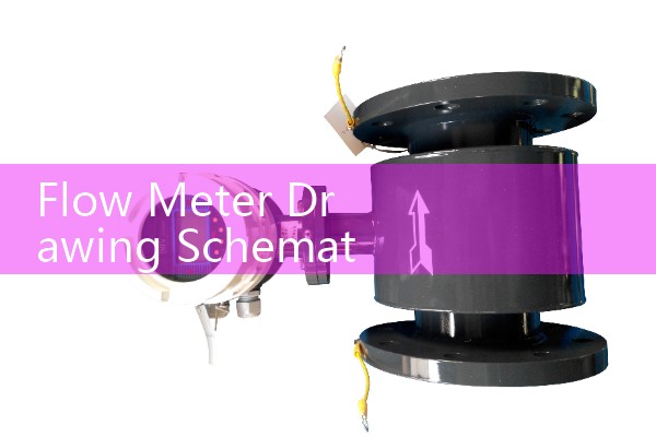
How to Request a Flow Meter CAD Template
Send us the following data and we will return the correct drawing set. Pipe size in DN or inches. Flow range in m3/h, kg/h, or L/min. Process fluid and viscosity in cP if the fluid is not water. Pressure in bar and temperature in °C. Process connection type such as flange, Tri-Clamp, thread, or wafer. Power and signal output such as 24 V DC, 4-20 mA HART, MODBUS RS485, or pulse. For hazardous areas, specify ATEX Zone 1 or Zone 2.
Example request from a project engineer in Peru last month. We need a DN50 Coriolis flow meter drawing for diesel with 4-20 mA HART and ATEX Zone 2. Operating pressure 8 bar, temperature 30 °C, flow range 500 to 5000 kg/h. We replied with PDF, DWG, and STEP files the same day.
Send your request by phone or WhatsApp. Tel: +86-25-68650347. Whatsapp: +86-25-52155837. WeChat: +86 15365082610. You can also reach us through flow-meter.com.au.
Which Drawing Fits Your Application
Water and wastewater engineers pick electromagnetic flow meter CAD templates. Steam and compressed air projects use vortex flow meter drawings. Chemical and food plants often need Coriolis flow meter schematics. Fuel distribution and marine service use oval gear flow meter drawings. Biogas and air flow projects use thermal mass flow meter insertion drawings.
Because we serve Southeast Asia, Oceania, Latin America, Africa, and the Middle East, we keep drawing sets that match common regional standards. Flange standards may be ASME, EN, or JIS. The CAD drawing notes the standard. If your project uses a different standard, tell us and we can adapt the drawing.
Common Mistakes When Using Flow Meter Drawings
Most engineers skip this part. They assume a flow meter is a straight pipe section. A Coriolis meter has two tubes and a transmitter housing that can rotate. A magnetic flow meter needs grounding rings or a liner protector for some pipes. The 2D top view alone does not always show the transmitter. The 3D model does.
Another mistake is ignoring cable entry orientation. A meter installed against a wall may have the cable gland on the wrong side. The drawing shows the cable entry view. Before finalizing the skid, ask for the correct orientation.
In practice, we recommend that the instrumentation engineer and the mechanical engineer review the same CAD file. This step catches conflicts between signal cable routing and pipe support location. A small gap in communication can cause a field modification.
FAQ
What CAD file formats do you provide? We provide PDF, DWG, DXF, and 3D STEP files for most flow meter models and pressure transmitters. Tell us the model and we will send the matching set.
Are the 2D drawings dimensionally exact? Yes. The drawings come from production records. They show face-to-face length, flange details, cable gland size, and height. You can use them for piping design and skid layout without redrawing.
Can I get a drawing before placing an order? Yes. Send the process data and pipe size. We provide standard drawings for evaluation. For a custom connection or special material, we prepare a proposal drawing after technical review.
Do you provide CAD drawings for hazardous area installations? Yes. For ATEX Zone 1 or Zone 2, the drawing set includes the Ex marking and installation notes. Local electrical codes still apply.
How fast can you send the drawing set? For standard products, we usually reply within 24 hours. Complex or customized models may take 2 to 3 working days. Send your request by WhatsApp +86-25-52155837 or reach us through flow-meter.com.au.
Tell us your process data and we will send the right flow meter drawing schematic for your engineering project.
 Hot News
 Related AD